
Speed Control of DC motor by Armature Resistance Control
STEP 1: Make connections as per the instructions given below:
| From | R | B | B | B | F | A | G | I | C | A1 | K |
| To | L | D | A2 | F2 | E | J | H | F1 | A1 | K | C |
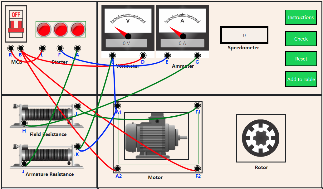
NOTE: If wire is wrongly connected, Click on node number to detach the wire.
STEP 2: Click on button for checking the connections.
STEP 3: Click on MCB to turn on the supply.
STEP 4: Now, move the second slider to get corresponding values of Voltmeter and Speedometer.
STEP 5: Click on button to add values to the observation table.
STEP 6: Repeat steps 4 to 5 to add more values in the table.
STEP 7: Click on button to make a respective graph regarding the values in the table.
STEP 8: Click on button to print the webpage.
STEP 9: Click on button to reset the webpage.