Instructions
STEP 1: Make connections as per the instructions given below:
1. (A1-A2), (B1-B2), (C1-C2), (E1-E2)
2. (F1-F2), (G1-G2), (D1-D2)
3. (K1-M1), (K1-K2), (K1-L1)
4. (H1-H2), (H1-I1), (J1-J2)
5. (J1-I2), (I2-M2), (M1-N1)
6. (N2-O1), (L1-L2), (L2-M1)
STEP 2: Click on “Check Connection” button to check the connections.
STEP 3: If the connections are not correct, you can click on node number to detach the wire or click on “Reset” button to make all the connections again.
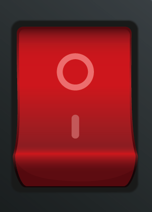
STEP 4: If the connections are correct, then Turn “ON” the MCB Switch.
STEP 5:Then, Click on the Auto Transformer knob.
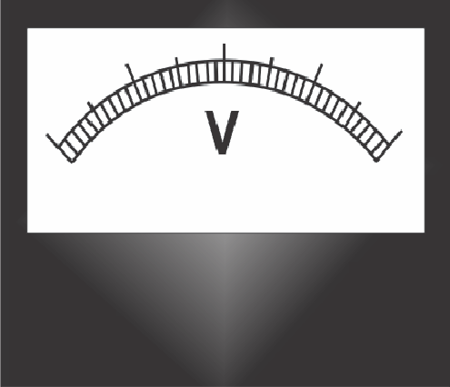
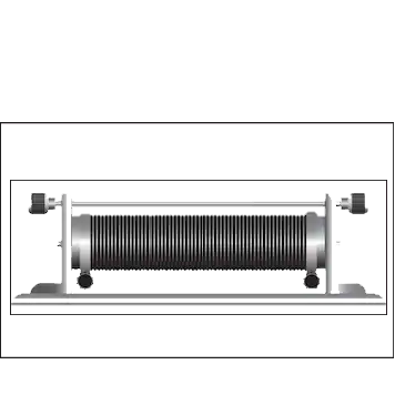
STEP 6: Now, Slide the Knob of the Rheostat. The readings of Voltmeter and RPM will be shown in the display.
STEP 7: Click on “Add to table” button to add the readings to the observation table and Live Graph will be created when readings are added in the table.
STEP 8: Click on “Print” button to print the webpage.
MCB Switch
DC Supply
Starter
Voltmeter
Auto Transformer
DC Generator Field Resistance
Induction Motor
DC Generator
DC Motor


